
Using the Euvis DSM API Through LabVIEW
Euvis module products, such as AWG’s, DSM’s, and DAQ’s, can be controlled through our companion API.
Users can develop their own applications with several CLR-based languages, such as C++, Java, Visual
Basic, etc, to control the modules via the API. These examples can be found on the individual
download pages of each product here.
Alternatively, the modules can also be controlled through widely used computation platform LabVIEW.
Requirements
LabVIEW does not support .NET 4.0 assemblies. To force it to load .NET 4.0 assemblies see the “Loading .NET 4.0 Assemblies in LabVIEW” on the National Instruments website. Follow the instructions given. If LabVIEW does not start once the configuration file is loaded, this may be due to unnecessary formatting text in the configuration file. Save the configuration file with the extension option as .txt so the there is zero formatting. Also, the Euvis API DLL, Euvis_Module_V2p0.dll must be directly on the computer, not accessed from a network.
Procedure
The following procedures were made using LabVIEW 2013. Procedures in LabVIEW 2011 should be similar. The source for these procedures can be found in the DSM_Example.vi file that can be downloaded at the bottom of this page.
Initialization
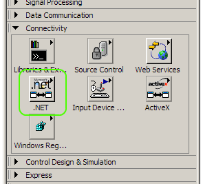
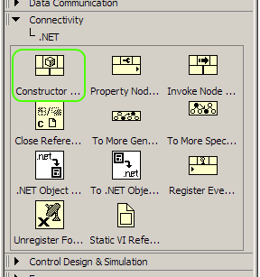
In a new blank VI, working with the Block Diagram window, place a Constructor Node inside the window. The block can be found under Connectivity --> .NET in the Functions palette.
This node will enable access to all the DSM classes and their methods and objects.
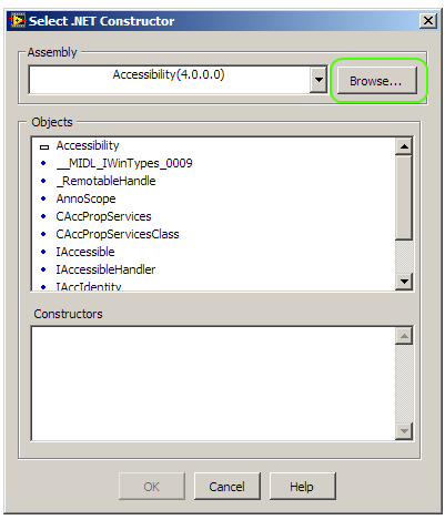
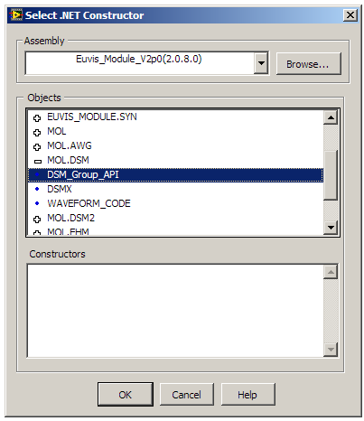
The first class to assign is DSM_Group_API. Once you have placed the constructor node in
the Block Diagram window, a menu will pop up. Click on “Browse”.
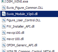
Go to the folder where you installed the Euvis DSM application (by default it is C:\Euvis\DSM\) and select
the Euvis_Module_V2p0.dll.
Once you have chosen the file and it has been loaded, the Objects window will populate with all the
namespaces. Double click on MOL.DSM, and then choose DSM_Group_API.
Once the class has been chosen, the .NET node in the Block Diagram window will change to reflect the class
name.

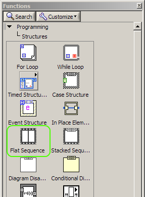
Now we need to create a sequence to get the serial number and initialize the DSM module to prepare it for
operation. To do this, first create a Flat Sequence structure, which can be found under Programming -->
Structures in the Functions palette.
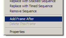
Create three frames to begin with by drawing a rectangle to create the first frame. Then right click the
frame and choose Add frame after. Add at least two frames.
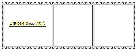
You should now have three frames. Drag and drop the DSM_Group_API node in the left-most
frame.
We can access the methods and properties in a class by right clicking on the node and selecting
“Create”. The first property we need to define is the Series Number of the DSM. Right click the
DSM_Group_API node and then select Create --> Method for
MOL.DSM.DSM_Group_API Class --> get_sn(Uint16 I).
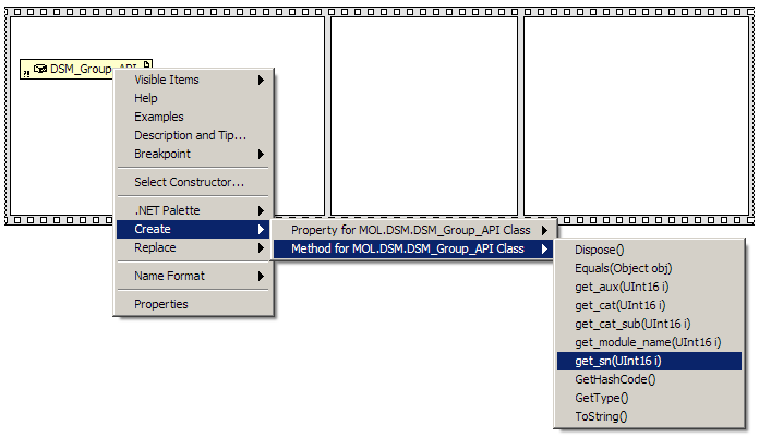
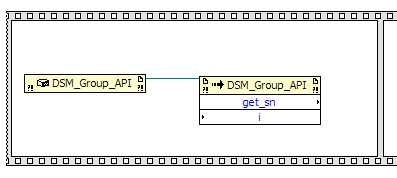
This creates an Invoke node, which invokes a method from a class. Place the new get_sn
node inside the first frame along with the DSM_Group_API node. Enlarge the frame if
needed. Wire new reference on the DSM_Group_API node to the reference on the
get_sn node.
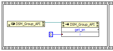
We want to get the Series Number of device 0 so we need to create a constant 0 and feed it into the input
of the get_sn node. Create a constant, which can be found in the Functions palette under
Programming --> Numeric --> Numeric Constant. Set the constant to 0 and wire it to the input of the
get_sn node.
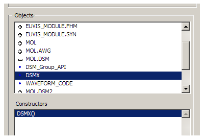
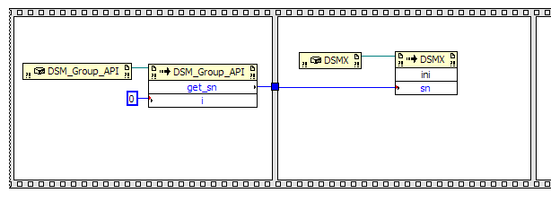
Create another .NET Constructor node, but this time choose the DSMX class.
Place this node in the second frame. Also, create an Invoke node for the method
ini(UInt32 sn) in the DSMX class and place it in the second frame as well.
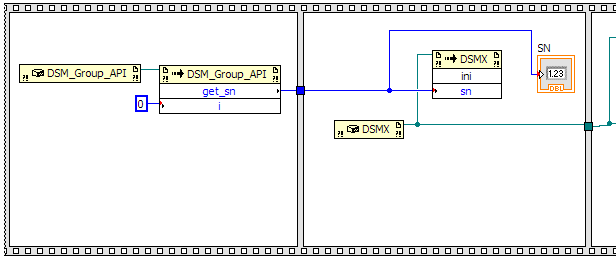
Wire the references together and then wire the output of the get_sn node to the input of the
ini node. The block diagram should look like the following image.
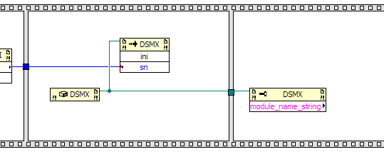
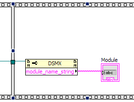
To determine if a module is initialized, you can create a module name and a Series Number indicator on the
front panel. To get the module name, create an Invoke node for property module_name_string
in the DSMX class and place it in the third frame. Wire the reference from the
DSMX Constructor node to the reference of the module_name_string node.
To create indicators, you will need to go the Front Panel window. To make the module name indicator, in the
Controls palette, select Modern --> String and Path --> String Indicator.
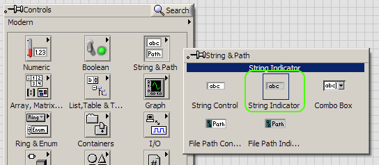
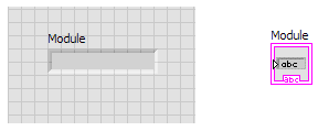
Place the indicator in the Front Panel window. A corresponding Indicator node will also appear in the Block
Diagram window.
In the Block Diagram window, place the Indicator node in the third frame and wire the output of the
module_name_string to the indicator.
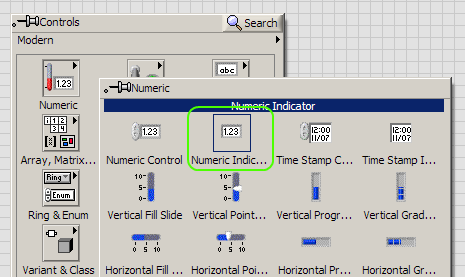
You can similarly add an indicator for the Series Number as well. Go to the Front Panel window and in the
Controls palette select Modern --> Numeric --> Numeric Indicator.
Place the indicator in the Front Panel window. A corresponding Indicator node will also appear in the Block
Diagram window.
In the Block Diagram window, place the Indicator node in the second frame and connect the output of the
get_sn node to the indicator.
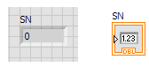
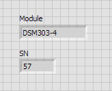
If you were to connect your DSM and run the VI right now, you would get something similar to the following
image in the Front Panel. Please note that your module name and Series Number may be different from what is
shown.
Creating and Running Waveforms
To create and run waveforms, you would just need to add successive sequential frames, define module and waveform properties, and call on methods to download and run the waveform. All relevant properties and methods can be found in the DSMX class. For more information on the properties and classes, please refer to the DSM API manual, which also includes a general usage guide. The DSM API manual can be found at the following link:
http://www.euvis.com/open/dsmapi/current/
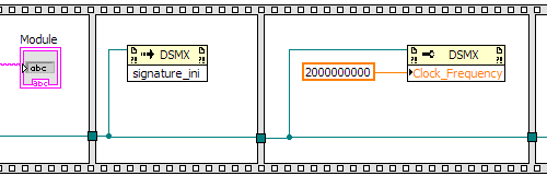
After initializing the DSM module, you will need to initialize signatures and load the correct signature for
your input clock frequency. The signature_ini method will initialize the signature and
defining the Clock_Frequency property will load the signatures for your clock frequency. Please note the
Clock_Frequency property is defined in double format. The signature frames are shown in the
image below.
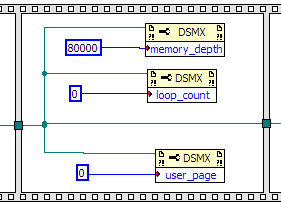
Next you will define the module operation properties. You will need to set the memory_depth,
loop_count, and user_page properties.
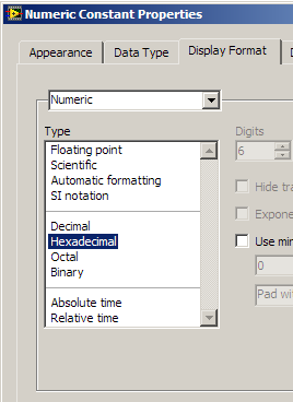
As a note, if you want to define any numeric constant as a hexadecimal, you can change it by right clicking on
the constant and then select “Display Format”.
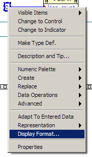
In the dialog box that appears, select “Hexadecimal”.
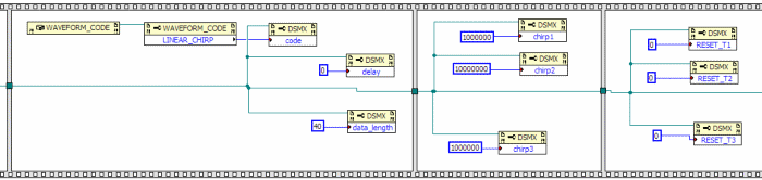
Next, we will need to define the waveform properties. These include the code,
delay, data_length, chirp1, chirp2,
chirp3, RESET_T1, RESET_T2, and
RESET_T3 properties.
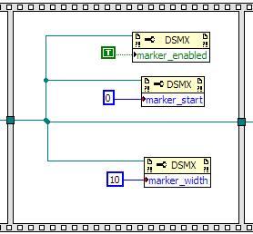
If you would like a marker, you can define the marker properties: marker_enabled,
marker_start, and marker_width.
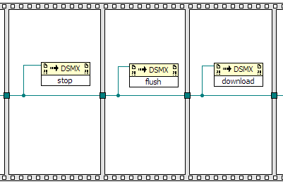
To download the waveform, you will need to run the following sequence of methods:
stop, flush, download
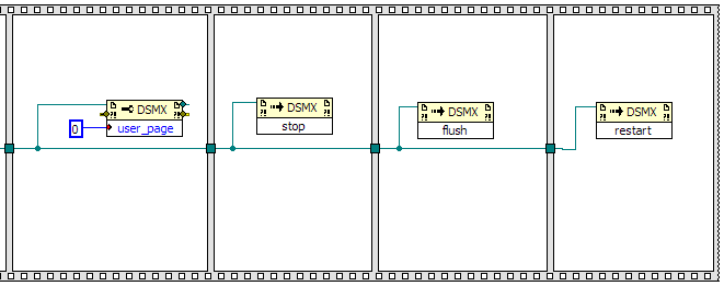
Finally to run the waveform, you will need to set the user_page property again to the user page you want
to run then run the following sequence of methods:
stop, flush, restart
If you were to connect your DSM and run the VI right now, you should get a waveform that is similar to
the startup waveform.
Downloads
A PDF version of the instructions above as well as the Example Code can be downloaded below in ZIP format.
| Name | Download | Size |
| Using Euvis DSM API Through LabVIEW Application Note and Example Code | ZIP | 1.37 MB |