First Powerup Checklist -
We have provided you a list of things you need to check for when you first use the AWG hardware and software. Going through this
list will ensure proper operation of the AWG in the future. After completing this list, please see the AWG251 Manual
for instructions to use the software.
1. Power Plug Connection
First you must make your own power plug to connect the power supplies to the AWG board. It is VERY important that you have the wires to the plug in the right order and that the wires are connected to the correct power supplies.
The power plug is rated for a maximum of 300V and 8A. The company that makes the plug suggests wire gauge that ranges from 16 to 24 AWG. We recommend that you use the thickest wire possible and therefore you should use 16 AWG wires. The strip length at the ends should be at least 5mm (0.2 inches).
We suggest that you either color code the wires or label them clearly so that you do not plug them into the wrong power supplies. We cannot emphasize enough the importance of the correct power supply connections. A wrong connection can potentially damage the board permanently.
The plug has flanges so that there is only one orientation in which the plug and the header can connect.

With the screws and tabs facing upward and the tabs facing to the right, connect the wires as indicated. Please strip at least 5mm (0.2 inches) of the wire and insert into the square holes on the opposite side of the tabs (on the left side in the image below).
After inserting each wire, use a 5/64" slotted screwdriver to tighten the screw holding the wire in place. Repeat this procedure for all six wires.
2. Power Supply Levels
After connecting the AWG board to the power supplies with the power plug, turn on the power supply. When you power up the power supplies, try to turn them on in the following order: +5V and -5V first then the +1.8V and +3.3V last. This is to ensure that the MUXDAC is ready before memory is turned on.
You must now check to see if there is any significant voltage drop across the power plug wires. You can check the voltage levels at the board by using a multimeter to probe the screws on the power plug which you used to tighten the wires to the plug. Both the grounds should be close to 0V and should not differ much from each other. The +5V, +3.3V, +1.8V and -5V supplies should all be close to their respective values and should not differ by more than a few hundredths of a volt. For example the 1.8V supply might be around 1.75V or 1.78V and these would be considered normal. But if the 1.8V had a reading of 1.69V then there is too much voltage drop across the length of the wire.
If you had connected the power supplies in the wrong setup then there is a high chance that there would be a short. If there is a short then the current reading on the power supply would be out of the normal range. Listed below are what we consider to be the normal current readings for each of the four power supplies:
| Voltage | Current Min | Current Typical | Current Max |
| +5V | 205 mA | ||
| +3.3V | 195 mA | ||
| +1.8V | 425 mA | 1.9 A | |
| -5V | 915 mA |
If any of the currents are out of range then it is possible that either the board has a physical defect or your power supply is connected wrong. First check to make sure that the power supplies are connected correctly. Even if you do correct the power supply connections after a wrong connection your board may not function anymore. In this case you will need to contact us.
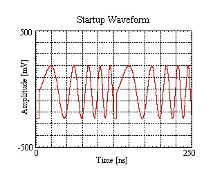
3. Initial Powerup Waveform
You will now need to check if the initial powerup waveform is correct. Connect your clock to the CKIP SMA near the upper left corner of the board, and set the frequency to 2 GHz. Then connect your oscilloscope to the OUTP SMA and your spectrum analyzer to the OUTN SMA at the upper edge of the board. You should see something like the following:
|

|
If you can see the waveforms correctly then you can go on to install the AWG software. If you can see a waveform but it does not look like the one above then try turning off the 1.8V and 3.3V power supplies and then turn them back on.
This is a good time to check that the 1.8V voltage has not dropped too low due to resistance between the module and your power source. At a clock rate of 2 GHz, the voltage measured at the power plug screw corresponding to 1.8V should be around 1.75V; if yours measures too low, please increase your 1.8V power source voltage slightly to compensate for the resistance of your wires.
If after a few tries the waveform still does not show up correctly then you will need to contact us for troubleshooting. Likewise, if you do not see any waveform at all then you will also need to contact us.
4. Software Installation
Please follow the instructions detailed in the Software Setup section of the manual. Please be sure to also check the Software Requirements section. After installation, navigate to the AWG program folder and check to see if there is a file called "AWG_SGN_0XX.dat" where XX is your AWG series number. This is the signature file that will allow you to switch clock frequencies without needing to adjust internal AWG settings for proper operation every time. If you do not have this signature file in the program folder, then you will need to contact us.
Since there will be different software for different boards, please make sure you have the right software for your board.
| HW Name | GUI | API | FW |
| AWG251 | 2.0.1 | 2.0.1 | 3.0.1 |
Series