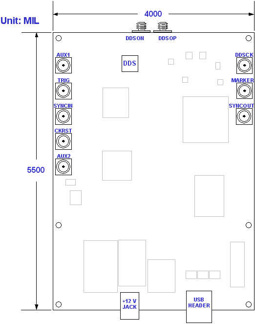
Board Layout -

The board dimensions are 4 inches by 5.5 inches. It is constructed by 4-layer sandwiched RO4003/FR4/RO4003 with a total thickness of 54 mil. The RF I/O’s are standard SMA connectors and the USB port is a type-B USB receptacle. Two heat sinks are applied to the DDS and the ASIC memory controller.
DDSOP / DDSON (SMA)
SMA connectors for output waveforms. The DDSOP connector should be connected to the oscilloscope since it outputs the positive phase. Spectrum analyzers can use either DDSOP or DDSON since frequency content is the same for both.
DDSCK (SMA)
SMA connector for input clock. Please connect to a clock source with minimum power of 0 dBm.
AUX1 / AUX2 (SMA)
Optional SMA connectors for either inputs or outputs. If options are not added, these two SMA connectors are non-functional.
TRIG (SMA)
SMA connector for trigger signal input. Trigger signal should be 3.3 V LVTTL or LVCMOS.
SYNCIN (SMA)
Used for Slave boards during multi-board operation. If the multi-board option is not added, this connector will be non-functional.
CKRST (SMA)
For Euvis internal use only. Please do not use this connector.
MARKER (SMA)
Programmable marker output. Signal is 3.3 V LVTTL / LVCMOS.
SYNCOUT (SMA)
Used for Master boards during multi-board operation. If the multi-board option is not added, this connector will be non-functional.
+12 V Power Jack
Provides the +12 V power supply for the DSM board. Please use the included AC adapter to connect to this jack.
USB Header
This is the USB B connector. You will need to connect this to a computer in order to communicate with the board.