
General Description:
The DSM303-V4 module generates arbitrary frequency chirping CW with frequency update rates up to 312.5 updates/microsecond (1/8 of the clock rate). At 2.5 GSPS, the module can generate frequency chirping in a bandwidth from DC to 1.25 GHz. The chirping profile can be linear or arbitrarily programmed. The DSM303-V4 can be controlled by a PC via GUI or by user application programs via API, or can work alone with pre-stored chirping waveform. The chirping waveform generations can be in Continuous, Triggered Continuous, and Triggered Burst modes. Up to 128 waveforms can be stored in user pages and pages can be switched on the fly.
Key Features:
- 3 GSPS DDS with 11-bit amplitude and 13-bit phase resolution
- Clock rate up to 3.0 GHz for CW and up to to 2.5 GHz for chirping
- Chirping standard sampling rate at 2.5 GSPS (2.5 GHz clock)
- Chirping optional sampling rate range from 1 to 2.5 GSPS (1 to 2.5 GHz)
- 520K X 32-bit words memory depth with maximum 128 different user waveforms
- Waveforms can be switched dynamically by selecting user pages on the fly
- Minimum waveform length of 256 ns in Triggered Burst Mode
- Maximum 1.6 millisecond chirping waveform at 2.5 GSPS
- Programmable phase reset for phase repetition
- Accepts external trigger and generates marker signal (programmable)
- 9 W power consumption (at 2.5 GHz clock) with +12V DC wall power supply (included)
- USB 2.0 compliant interface (USB cable included)
- Other interfaces available upon request
- Companion API and software drivers for easy system development
- API compatible with Matlab 2010a
- API compatible with LabView
Applications:
- FM chirp source for radars
- Agile LO frequency synthesis
- Electronic warfare
- RF signal source generation
- Fast frequency hopping
- VSAT satellite communications
- Test and measurement equipment
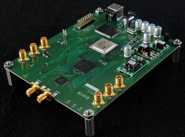
Board Photo:
Graphical User Interface Application:
» To download the DSM Software, API, and Manual, please click here.
Example Waveform Outputs:
|
|
|
| Photo 1 | Photo 2 | Photo 3 |
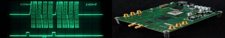
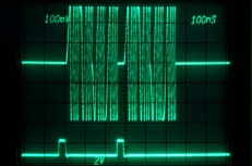
In Photo 1, the DSM303 is chirping 4 segments back to back continuously in one waveform. In each segment, the module
is chirping from 7.8125 MHz all the way up to 125 MHz in 7.8125 MHz steps. The frequency update rate is 250 MHz. The
total waveform length is about 288 ns.
In Photo 2, the DSM303 is chirping the same waveform as in Photo 1 but the waveform is looped twice. Once the first
waveform finishes the next waveform is immediately started with no latency. The total waveform length is exactly
double as that in Photo 1 and is about 576 ns.
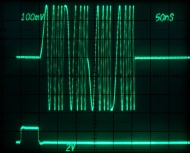
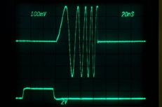
In Photo 3, the DSM303 is chirping only 1 segment. The total waveform length is only about 96 ns.
Detailed Specifications:
| GENERAL | |
| DDS Frequency Resolution | 32 bits |
| Frequency Update Rate | 1/8 of Input Clock |
| Waveform Generation Modes |
Continuous
Triggered Continuous Triggered Burst / Pulse |
| User Interface | Windows GUI, USB |
| INPUT CLOCK | |
| Type | Single Ended |
| Termination | 50 Ω |
| Connector Type | SMA |
| Frequency Range Static | 1.0 GHz to 3.0 GHz for static operation |
| Frequency Range Chirping |
Standard: 2.5 GHz
Optional: 1.0 GHz to 2.5 GHz |
| Power Level | 3 dBm to 18 dBm |
| Return Loss | 13 dB |
| OUTPUT | |
| Type | Single Ended or Differential |
| Termination | 50 Ω |
| Connector Type | SMA |
| Output Sampling Rate Range |
Standard: 2.5 GSPS
Optional: 500 MSPS to 2.5 GSPS |
| Output Maximum Frequency |
Standard: 1.25 GHz
Optional: 250 MHz to 1.25 GHz |
| Output Level | -635 mV to 0 V |
| Output Power | -4 dBm to 0 dBm |
| Residual Phase Noise @ 10kHz from Carrier | -145 dBc/Hz |
| Output Return Loss | 15 dB |
| WAVEFORMS | |
| Max Waveform Length |
523,264 words in Continuous Modes
519,176 words in Burst Mode |
| Minimum Waveform Length |
32 frequency words in Continuous or Triggered Continuous modes
256 ns in Triggered Burst mode |
| USER PAGES | |
| Maximum Number of User Pages | 8 |
| Frequency Words per Page | 4092 words |
| TRIGGER | |
| Connector Type | SMA |
| Source | External or Internally Software Generated |
| External Trigger Logic | LVCMOS33 |
| Minimum Trigger Period | 1 us |
| MARKER | |
| Number of Markers | 1 |
| Marker Length | User defined |
| Marker Output Logic | LVCMOS33 |
| API | |
| Version | Euvis API 2.0 |
| CLR Language Support |
Visual C++
Visual C# Visual Basic Visual J# |
| GUI | |
| Available for Windows XP, Windows Vista and Windows 7 | |
| OPTIONS | |
| Variable Input Clock Frequency Range from 500 GHz to 2.5 GHz | |
DSM Waveform Generation Modes:
The module can be operated in three waveform generation modes: Continuous mode, Triggered Continuous mode and Triggered Burst mode.
Continuous Mode
In Continuous mode, the module starts waveform generation by a Restart command from the GUI or API-based
application. Once the waveform starts, the module repeats the waveform continuously. There is no latency between
two consecutive waveforms. The following waveform starts right after the end of the preceding waveform. The waveform
generation can be aborted by an Abort command from the GUI or API-based applications.
Triggered Continuous Mode
In Triggered Continuous mode, the operation manner is similar to that in Continuous mode
except for the start of waveform. The waveform generation is initiated by a trigger signal. In order to accept the
upcoming trigger signals, the module has to be armed prior to the instance of the trigger signal. Trigger signals
occurring before the module is armed will be ignored. An Arm command from the GUI or API-based applications
can be used to arm the module. Once the module is armed, it waits for the trigger signal. The waveform generation
starts after the falling edge of the trigger signal. The trigger signal can be applied via the TRIGGER SMA
connector or provided by a command Trigger via the GUI or API-based application.
Triggered Burst / Pulse Mode
In Triggered Burst mode, the module starts waveform generation when it is armed and receives the trigger
signal as in the Triggered Continuous mode. Instead of repeating continuously, the waveform starts, repeats,
and stops after finite repetitions. The number of the repetitions can be specified by the property Loop Count
via the GUI or the API-based application. The Loop Count can be set from 1 to 255. Trigger signals occurring before the
module is armed will be ignored. Similarly, trigger signals will be ignored if the module is in the middle of a waveform.
Once the waveform stops, the module will arm itself automatically and wait for the next trigger signal.
The following figure shows waveform generation for different Loop Counts: 1, 2, and 3.
Board Diagram:
Detailed Datasheet:
To get the complete DSM303 datasheet, please click here.
Email to: info@euvis.com to get pricing information.