Hardware -
Requirements
- -5V power supply capable of 1 A current
- Clock source
- Spectrum Analyzer
- Oscilloscope
Setup
DC Connections
-
-5 V Supply
- Connect the –5V power supply output to the N5V pin on the board.
- N5V uses a red DC pin and is located on the top right side of the board.
-
Ground Supply
- Connect the ground to the GND pin next to the N5V pin.
- GND uses a black DC pin and is also located on the top right side of the board
- DO NOT connect to the P33V (+3.3 V) DC pin. This is for the USB controller but it will be self powered through the USB cable.
RF/SMA Connections
-
Clock Input
- Set clock DC level to ground or use a DC block for AC coupling.
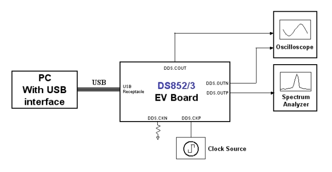
- Feed the clock to board at DDS.CKP located on the right edge of the board.
- Terminate DDS.CKN with a 50 Ω termination
-
RF Outputs
- Connect DDS.OUTP to the Spectrum Analyzer
- Connect DDS.OUTN to the Oscilloscope
» Using the USB A to B cable, connect the DDS device to the computer. Both LEDs "L1" and "L2" should light up.
Testing Setup Block Diagram