Hardware Requirements-
- DSM Board
- PC with USB 2.0 port
- USB A to B Cable
- Clock source capable of 3 dBm signal
- Oscilloscope
- Spectrum analyzer
- Power supplies capable of 4 different outputs
- Six 16 to 24 AWG wires
- At least 3 SMA cables for clock source, oscilloscope and spectrum analyzer
- More SMA cables will be needed if you intend to use synchronization
Power Plug Setup
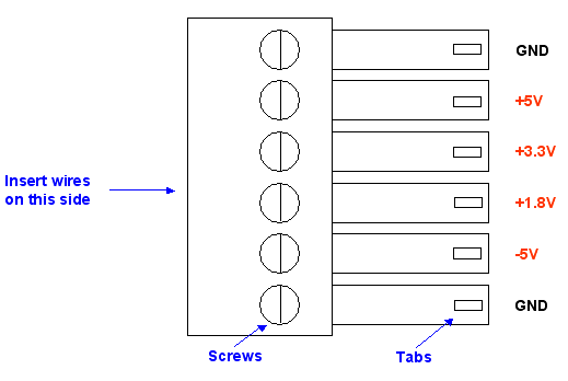
For your convenience we have provided a plug and header configuration for easier power supply connections to the DSM board. It is VERY important that you have the wires to the plug in the right order and that the wires are connected to the correct power supplies.
The power plug is rated for a maximum of 300V and 8A. The company that makes the plug suggests wire size that range from 16 to 24 AWG. The strip length should be at least 5mm (0.2 inches)
We suggest that you either color code the wires or label them so that you do not plug them into the wrong power supplies. We cannot emphasize enough the importance of the correct power supply connections. A wrong connection can potentially damage the board permanently.
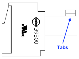
The plug has tabs so that there is only one orientation in which the plug and the header can connect.

With the screws and tabs facing upward and the tabs facing to the right, connect the wires as indicated. Please strip at least 5mm (0.2 inches) of the wire and insert into the square holes on the opposite side of the tabs (on the left side in the image below).

After inserting each wire, use a 5/64" slotted screwdriver to fix the wire in place. Repeat this procedure for all six wires.