Hardware Setup-
Outputs
» Connect your oscilloscope and spectrum analyzer to the OUTP and OUTN SMA connectors. They are 50-ohm back terminated, so you can connect one or both, in either order.
Clock Source
» Set your clock to the desired frequency with 3 dBm power. Connect your clock to the CKIP SMA connector at the upper left corner of the board.
Power Plug Setup
For your convenience, we have provided a plug and header configuration for power supply connections to the AWG board. It is essential that you connect wires from the plug to the power supplies in the correct order.
The power plug is rated for a maximum of 300V and 8A. The plug manufacturer suggests wire size that range from 16 to 24 AWG but we recommend you use either 16 or 18 AWG wires to reduce significant voltage drops across the wires. The strip length for the wires should be at least 5mm (0.2 inches) for the end that will go into the power connector.
We suggest that you either color code the wires or label them so that you do not plug them into the wrong power supplies. We cannot emphasize enough the importance of correct power supply connections. Any wrong connection can potentially damage the board permanently.
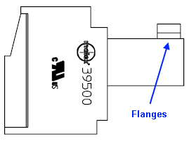
The plug has flanges so that there is only one orientation in which the plug and the header can connect.
With the screws and flanges facing upward and the flanges on the left side, connect the wires as indicated. Please strip at least 5mm (0.2 inches) of the wires and insert them into the square holes on the opposite side of the flanges (on the right side in the image below).
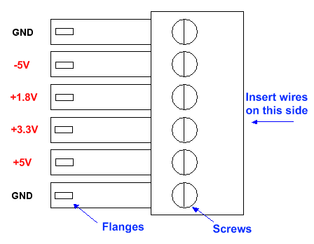
After inserting each wire, use a 5/64" slotted screwdriver to fasten the wire in place. Repeat this procedure for all six wires.
Power Supply
IMPORTANT: Do not turn on the outputs to the power supplies just yet. First set the voltage and current limits to the following:| Voltage (V) | Current (mA) |
| -5.0 | 2500 |
| +5.0 | 450 |
| +3.3 | 250 |
| +1.8 | 2000 |
» Insert the power plug into the power header near the upper right corner of the board. You should have already set up the plug so that the wires are connected to the power supply in the correct order.
NOTE: The current on the -5 V and 1.8 V supplies are very large, so the wires should be of high quality and low resistance to avoid voltage drops along the wire and subsequent performance degradation.
After you have connected the power supply and turned it on, you should use a multi-meter to check the voltages at the connector just in case there is a significant voltage drop across any of the wires. You can check the voltage at the connector by probing the screw which you used to fasten the wires. Both the grounds should be near 0 V. The +5 V, +3.3 V, and -5 V supplies should all be close to their respective values. The 1.8 V should read approximately 1.75 V. If any of the readings at the connector are not correct, adjust the power supply until the reading is correct.
NOTE: When unplugging the power plug from the header, pull the actual plug and not the wires to avoid disconnecting the wires from the plug.
USB port
» Connect the AWG board to your PC with a USB cable only if you have already installed the software and drivers.
» If you have not installed all the software and drivers, please do not connect to the USB port. You can still operate the board in standalone mode.
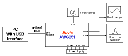
» Schematically, the connections should look like the diagram below:
Power On
» Turn on the power supply. You may turn on the power supply in any order.
» If you have done everything correctly, then you should see the built-in waveform output on your
oscilloscope and your spectrum analyzer after a few seconds.
The built-in waveform is pre-stored in the firmware and is automatically loaded at startup.
Even with a PC connected to the AWG, the built-in waveform loads and
runs before the PC
downloads a new waveform to the board, although
you must press the Restart button in the AWG_WIN.exe application once you have started
the program.
The built-in waveform is a 256-point cyclic linear chirping waveform sweeping from 1/256 to 1/16 of the clock frequency with frequency update at 8 clock cycles.
» The built-in waveform can be customized upon request.