User Defined Waveforms
You can create your own waveforms by loading a custom user defined waveform into the GUI application. To load the file, go to the Waveforms panel and choose the User_Defined (user_defined.wfa) waveform in the drop-down list. Or, select any predefined waveform, and then enter "256" into the Waveform Code box.
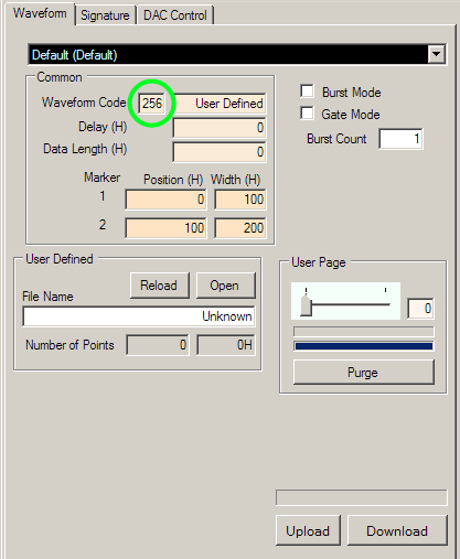
Then, in the User Defined parameters section, click on Open and load the .uda file that you have created. The Data Length will automatically adjust as long as it is specified in the ".uda" file header.
User Defined Waveform Files
To create a user defined waveform file you will just need to fill a text file with the waveform information and save the file with
a ".uda" extension.
Click on the file below to see what a user defined waveform file looks like:
For the "#type" there are only two options. If you want to use the GUI to control the markers then you should use "#type=1". By using this type, you can only control the markers with the two marker boxes in the Waveform tab. The other option is to use "#type=5" as was used the example. In this case, you should specify the markers using the second column of the .uda file.
The "#hex=1" signifies that all data are entered as hexadecimal. This is the only data format that you should use.
The first column of the .uda user defined file determines the amplitude of the output.
For the AWG474, the MUXDAC has 10 bit amplitude resolution, so you
should specify the amplitude within the range from 0 to 3FF (hexadecimal).
The second column is optional and only relevant when you use "#type=5". This column specifies the two marker outputs. You can think of the two markers as two bits. The LSB is for Marker 1 and the second LSB is for Marker 2. To set any of the markers active you would just set that bit to "1". Therefore when you want to set Marker 1 active, you would set the second column to "1". If you wanted both markers to be active then you would set the second column to "3". The table below shows the different options for the markers:
| Setting | Marker 2 | Marker 1 |
| 0 | Off | Off |
| 1 | Off | Active |
| 2 | Active | Off |
| 3 | Active | Active |
Unlike the marker settings in the GUI, you can have any of the markers go active multiple times during each waveform. In addition, the marker is active for every thirty-two data points, and you must have the marker active on the first of the thirty-two data points. If the marker is set to active on the second, third or fourth data points, but not the first, then the marker will not be active. For details about the three available markers, please see the Parameters page of the Operation Details section.