Hardware Setup
Outputs
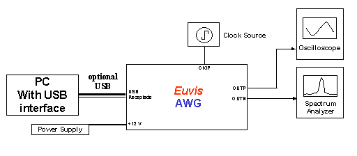
» Connect your oscilloscope and spectrum analyzer to the P and N SMA connectors. They are 50-ohm back terminated, so you can connect one or both, in either order.
Clock Source
» Connect your clock to the CK SMA near the upper left corner of the board, and set the frequency and power level to (typical operating specifications):
- AWG474: 4 GHz with power +9 dBm
» For optimal performance, the clock source should have sharp transitions.
Trigger (optional)
» For single-module free running operation, you do not need a trigger signal. For multi-module operation, or for operation in a triggered mode, you may want to use a trigger source so that the master module will generate a SYNCO signal periodically. Set your trigger source, such as a function generator, to a 1 kHz square wave with 1 Vpp amplitude and 0.5 V DC offset (for a 50 ohm load; set the amplitude higher if your setting is for high impedance). Connect your trigger source to the TRIG SMA connector on the back of the module.
Power Supply
The AWG TRX requires one +12V input which is provided by the included 120V-240V AC power adapter which can be plugged into any compatible wall socket. Insert the barrel end of the power supply to the connector marked +12V on the back of the AWG module.USB port
» Connect the AWG TRX module to your PC with a USB cable only if you have already installed the software and drivers.
» If you have not installed all the software and drivers, please do not connect to the USB port. You can still operate the board in standalone mode.
» Schematically, the connections should look like the diagram below:
Power On
» Flip the switch to the "ON" position to power up the AWG
TRX.