Markers
Markers can help you determine if the output waveform is correct. We have provided two markers accesible from the MARKER1 and MARKER2,
SMA connectors on the back panel of the AWG.
The marker settings are in the Waveform panel, just below the Data Length box.
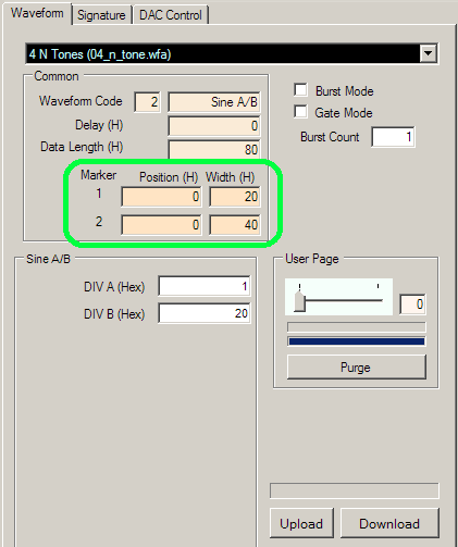
Marker 1 is 1.8 V TTL (rail-to-rail) logic level while Marker 2 is 3.3 V LVTTL (rail-to-rail) logic level. Marker 1 has less delay than Marker 2. For details about the three available
markers, please see the Parameters page of the Operation Details section.