Gated Mode
In Gated mode, the operation manner is similar to that in Free Run/Continuous except the output of the AWG TRX is only enabled on a "High" trigger signal.
In this mode, waveform generation is initiated as if in continuous mode. However, waveform output does not occur except in response to a high trigger. The module begins producing a waveform and is armed to wait for the trigger signal.
The waveform output occurs on a high value of the trigger signal. The trigger signal can be applied via the TRIG SMA connector or provided by a command Trigger via the GUI or API-based applications. Due to the asynchronous timing between the upcoming trigger signal and the module clocking, there will be some uncertain delay/latency between the trigger and the waveform generation. However, the waveform generation is synchronized with respect to the module clock.
After waveform generation has begun, the module proceeds as if in Free Run/Continuous mode. It will repeat the waveform continuously. There is no latency between two consecutive waveforms. The following waveform starts right after the end of the preceding waveform. The waveform generation can be aborted by an Abort command from the GUI or API-based applications.
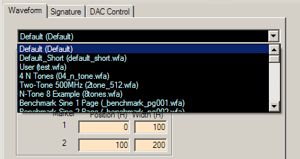
» With the program open, click on the Waveform tab if you are not already in the Waveform Panel.
» Click on the drop-down list and select one of the saved waveforms, such as "1/32 Sine (sine_1o32.wfa)", which is a Sine wave at 1/32th of the clock frequency. The files have the extension .wfa and are stored in your application folder or the user-defined waveform directory. You can adjust various parameters if desired.
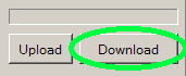
Click on the Download button near the bottom of the window or in the toolbar. Wait several seconds for the file to finish downloading.
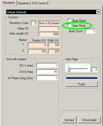
Click the Gate Mode checkbox in the waveform tab to enable Gate Mode. Connect the TRIG SMA connector on the rear panel of the AWG TRX to the desired gate signal generator using a standard SMA connector. It is recommended that the gate signal use a LVCMOS/LVTTL 2.5 V standard.
Finally, apply a trigger signal, via the TRIG SMA on the module