Synchronization -
Please note that multiple board operation is an option and is not included in the base DSM configuration
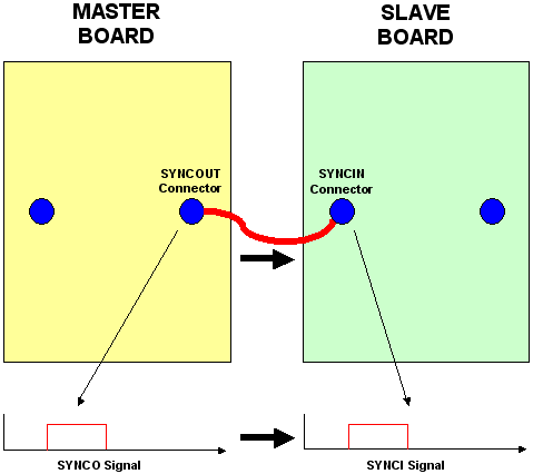
Synchronization between two boards is done through the SYNCOUT and SYNCIN connectors. We call the signal sent through the SYNCOUT connector SYNCO and the signal sent through the SYNCIN connector SYNCI so we do not confuse the connectors and the actual signals. For multiple board operation, there must always be a Master board. The Master board will send out the SYNCO signal through the SYNCOUT connector and the Slave boards will receive that signal through their SYNCIN connectors. Inside the Slave boards, the signal from SYNCIN is called SYNCI. The Slave SYNCI signals will always match the Master SYNCO signal.
It is important to note that waveform generation starts ONLY based on the SYNCI signal, even in the Master board and when in Standalone operation. The user may then wonder where does the Master board or the Standalone / Free Run board receive its SYNCI signal? When the Internal SYNCI option is checked the SYNCI signal would mirror the internally generated SYNCO signal.
The diagram below illustrates the signal timeline of a Master and Slave board with the Internal SYNCI enabled on the Master board. The board is assumed to already have been in the "Armed" state.
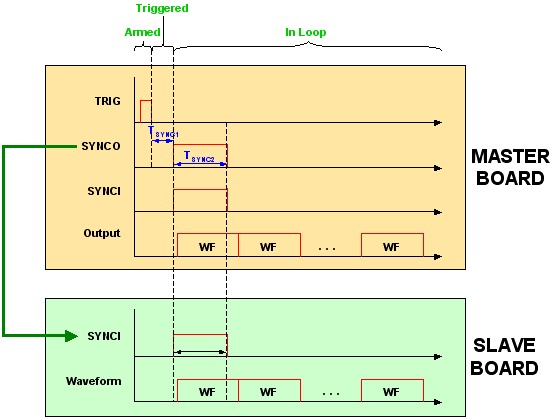
The "TRIG" signal at the top can represent either the input at the TRIG connector the use of the hardware TRIG button on the Master
board or the use of the software trigger in the Master board GUI.
Before the rising edge of the SYNCI signal, the board is considered to be in the ōTriggeredö state.
The SYNCI signal mirrors the SYNCO signal so both signals are always the same if Internal SYNCI is enabled. In the above diagram, the ōSYNCOö represents the SYNCO signal of the Master board while the ōSYNCIö represents each of the SYNCI signals of the Master and Slave boards.