Triggered Loop (Master) Mode -
In Triggered Loop mode, the DSM will output a defined number of waveforms for each trigger signal that it receives.
In Triggered Loop (Master) mode, the minimum chirp time for one loop should be 24 microseconds. Therefore the minimum Data Length will depend on the input clock frequency. At 2 GHz, 24 microseconds is about 6000 points so the minimum Data Length is 0x1770 or 6000. To determine the minimum Data Length for Master or Slave mode use the following formula:

Triggered Loop Mode Operation Example:
» Power up the DSM board by turning on the power supplies. Remember that you should turn them on in the right order as specified in the Hardware Setup page. When the board powers up, you should see the demo waveform displayed in the oscilloscope with the corresponding spectrum in the analyzer.
» Open the DSM application. Upon loading, the board will stop producing the demo waveform. Set the
Clock Frequency in the "Signature" tab to the correct frequency.

» Click on the "Configuration & Status" tab to go to that window. Change the configuration so that only
Master is checked.

» Change the Loop Count to "3". The DSM will output the waveform 3 times in a row for every trigger
signal that it senses. Also make sure that Auto Armed is checked.

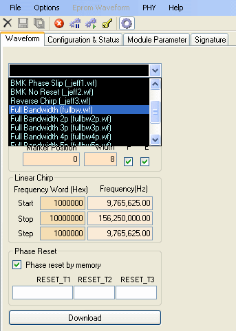
» Click on the "Waveform" tab to go to that window. Click on the drop-down box and click on the "Full Bandwidth" waveform.

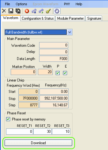
» The "Full Bandwidth" waveform parameters will load. Click on "Download" to send the data to the DSM hardware.

» You will need to "arm" the board before starting the trigger signal. To arm the board, either click on the "Arm" button
on the GUI or press F2 on your keyboard.

» Assuming you have not yet started the trigger signal your Status should look something like the image below. To get the
status of the board click on the Update Status button.
The "Auto Armed" and "Armed" boxes should be checked. This means that the board is
in the Armed state and is awaiting a trigger signal to begin waveform output.

» At this point you will either need to provide a trigger signal or you can press the TRIG button on the DSM board. The
trigger signal we used in our lab was a 500 Hz 1 V peak-to-peak square wave with a DC offset of 0.5 V. You should use a similar signal
for your trigger. The frequency of the trigger of course is up to you.

» Once the board receives the trigger signal, you will see the output in the oscilloscope and the spectrum analyzer. Using
the oscilloscope you can verify that there is indeed three waveforms in a row being output.
» If you go to the "Configuration & Status" window and click on "Update Status" repeatedly, you will notice
the board in various states of operation. If you click on Update Status at the right moment, you should
see that the board is in the Triggered and In-Loop states.
