Enclosure Diagrams
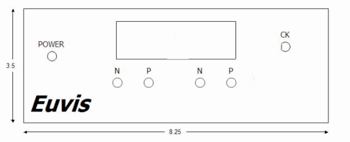
AWG474 Front Panel
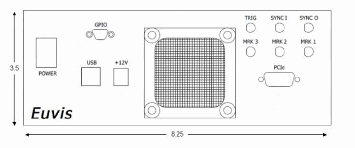
AWG474 Back Panel
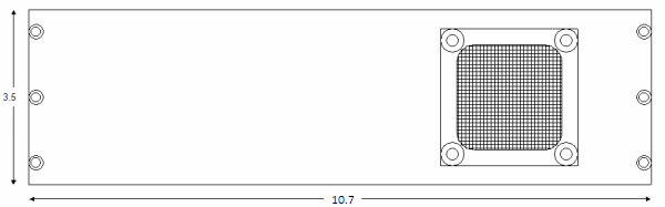
AWG474 Side Panels
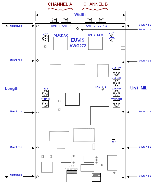
| Description |
|
P / N (SMA)
SMA connectors for output waveforms. They should be connected to an oscilloscope and a spectrum analyzer. If only using one output, please terminate the unused output with a 50 ohm termination. |
|
CK (SMA)
|
|
TRIG (SMA)
Optionally connect a trigger signal source to the AWG board. For more information on synchronization, please go to the Synchronization section. |
|
SYNCI (SMA)
|
|
USB receptacle
|
|
+12V
|
|
Power Switch Toggles power on the module between On (I) and Off (O). |
|
SYNCO (SMA)
|
|
MARKERS (SMAs)
|
|
Power LED Indicates the power status of the module. Off: AC adapter is not connected. Red: AC adapter is connected but the power switch is in the off position.
Yellow: Module is powered on. |
Note: Some modules may refer to SMA connectors differently (i.e. OUTP = P = OP; CKIP = CK; etc...)