Waveform Panel
The Waveform panel is accessed by the first tab. In this panel you can load various pre-stored waveforms, adjust parameters of those waveforms, and select the memory address page.
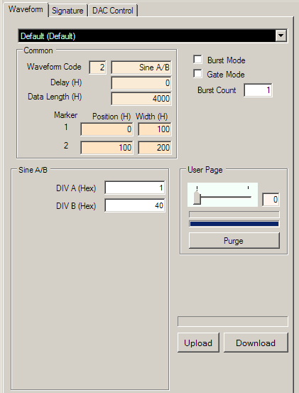
Waveform Selector
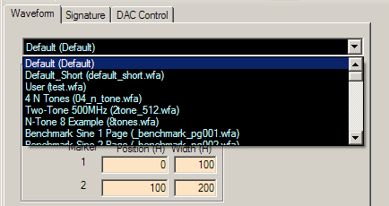
Click on the drop-down list to select a waveform. The software comes with several
pre-defined waveforms and you can
make your own waveforms to put on this list. Please
see the Save Waveform section.
Waveform Parameters
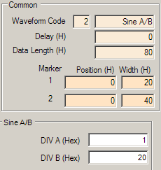
Waveform Code
Specifies the style of waveform to be implemented. Each style has corresponding
specific parameters to adjust the waveform. These parameters may be entered in a
section below Common parameters only after you have entered a waveform code.
For more details about this, please go to Waveforms
in the Waveform Files section.
Delay
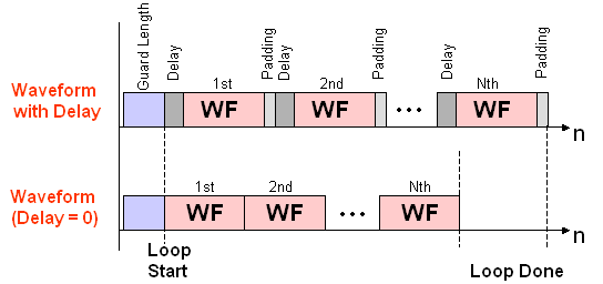
Specifies waveform delay in terms of memory addresses. This is defined in hexadecimal code. Increasing the Delay by 1 delays the desired waveform output by 1 clock (1 sample). For example, if delay were set at "5", the first 5 memory addresses would have the first data value of the waveform, and then at the 6th memory address the waveform amplitude changes would begin.
If you use a non-zero Delay, the total waveform length will be increased by the
Delay plus padding at the end of the desired waveform to ensure that the output
total waveform length is a multiple of 40 (hex) for the AWG474. The Delay and padding will repeat every waveform
cycle, so there will appear to be a gap between repeated bursts
when in Continuous mode and when in Burst Mode when Burst count is larger than 1.
Data Length
Specifies how many memory addresses to use for the waveform. This is defined in hexadecimal code, and the Data Length must be a multiple of
- 40 (hex) for the AWG474
NOTE: If you wish to use dynamic paging, which offers up to 256 user pages depending on the data length of the waveforms, there are some considerations to make with your Data Length. The maximum number of user pages can be used only if each user page length is less than one uPage. If you use several uPages in any waveform(s), there will be fewer user pages available for use.
Markers
The AWG TRX module offers two marker signals. Markers are useful for identifying waveforms, since the markers are generated simultaneously with the waveforms. These parameters specify where and how long to output the markers.
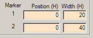
The Position box specifies the data point where you would like to start the marker. The
Width specifies how many data points you would like the marker to be active.
The different characteristics of the two markers are detailed in the
Parameters
page of the Operation Details section.
The Marker is useful as a diagnostic tool. Markers are ONLY output when there is waveform generation. If you have marker enabled but you have no Marker signal then it means that there is no waveform output.
Paging
The AWG TRX module features memory address paging. You can set which user page to use here in this panel (for details, see the description of Multiple waveforms with paging).
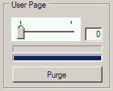
Each user page can load a separate waveform, but the more pages you have, the fewer memory addresses you have available for each waveform -- meaning the maximum data length of each waveform is shorter. Or, the longer the data length of each of your waveforms, the fewer the number of user pages you will have available. The total number of memory addresses is fixed.
Download Waveform
Click this button, located near the lower edge of the waveform panel, to send current waveform parameters to the board. You will have to use this button whenever you change any
waveform parameters.
After a waveform finishes downloading, press the Play button to enable the AWG TRX outputs.